Anchor Deployment Rules
Please go through this section carefully in order to ensure the best possible location accuracy.
Installation of Anchor Apollo
Anchor Apollo (Wired/Wireless both) has got omnidirectional antenna. Therefore, it must be installed with the antenna upright or in some cases inverted. On the picture below you can see the radiation pattern of the omnidirectional antenna in Anchor Apollo. To obtain the best performance it is crucial to place the anchor correctly.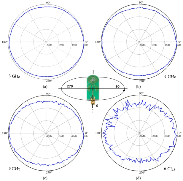
Tip: Place the Anchors ideally at the same height.The best deployment strategy is to place the anchors at the same height within one tracking area. If the premises does not allow it try to keep them at least roughly within the same level, max. 50 cm difference. The absolute height should not exceed 5 meters above Tags, applies for both Anchor Apollo Wired and Wireless.
Note: Keep distance between Anchor and walls/ceiling**Always use the anchors holders provided in the Locator Kit. Never place the anchors right on the wall or ceiling as it may affect the anchor’s antenna radiation pattern and decrease its radio performance significantly. If the anchor is close to a ceiling as shown on the picture above install the anchor in vertically upside-down position.
Correct placement examples
Below are few examples of placing the Anchor Apollo correctly. (Placeholder: Series of images showcasing correct Anchor Apollo placements: e.g., 1. Upright on a wall using the holder. 2. Inverted from a ceiling. 3. Mounted on a pole.)Incorrect placement examples
Below are few examples of placing the Anchor Apollo incorrectly. Do not install the anchor in a horizontal position , it will degrade the radiation pattern and overall Anchor’s performance. (Placeholder: Series of images showcasing incorrect Anchor Apollo placements: e.g., 1. Lying flat on a surface. 2. Tilted horizontally.)VESA Support
The Anchor Apollo support off the shelf available standard VESA mounts. The Locator Kit is delivered with a VESA bracket of (75x75 mm) as an additional accessory to the kit. More details about mounting Anchor Apollo can be found in Assembly & Mounting (Placeholder: Image showing the VESA mounting points on the Anchor Apollo and an example of a VESA bracket attached.)Installation Rules
1. Always keep a clear line of sight between the master anchor and neighbor anchors (slaves) within location cell.
The master anchor should always have a clear line of sight to at least three other slave anchors in its vicinity. It is not required to ensure line of sight between all slave anchors in the system just in the same location cell. Each location cell must have its own master (Either primary master or secondary master). In complex multi-master deployments every master should have clear line of sight to at-least one master. Master selection is done via RTLS Hub Software. (Placeholder: Diagram illustrating a location cell with a master anchor having clear line of sight to at least three slave anchors. Another diagram showing two linked master anchors in a multi-master setup.)2. Deploy the anchors above all the objects that are being located.
The anchors use UWB wireless synchronization, this means that they need a clear line of sight between each other. Therefore, it is best to mount them above any moving objects including the objects that are being tracked.3. Keep a square geometry during the deployment.
Due to dilution of precision phenomena, the best approach is the “squaring” the location cell. The ratio between the two sides should not be higher than 3:1 to achieve highest possible accuracy. The squaring of cells can be either physical or virtual. Some areas like narrow aisles can be covered using a zig-zag deployment. The downside of this type of deployment is that it decreases accuracy in narrow sections, RTLS RF Planner clearly demonstrates the impact of such geometry on precision.4. Try to maintain a direct line of sight between the tag and the anchors → if the tag deployment is not ideal then higher density of anchor placement is needed.
- Find the highest point of asset with minimum metal shielding and bolt the tag onto the surface.
- Find a spot with minimum body mass for Tag placement on a person.